Page updated on Monday, July 17, 2026


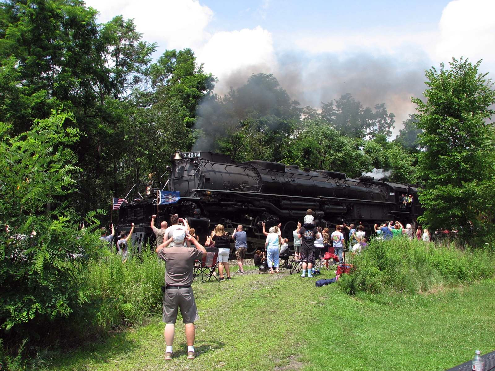
On July 11th, the Union Pacific Big Boy headed west from Altoona.
I was able to see it roll by in Derry PA.
Latest work completed:
Not as much getting done in the warmer months with all the outdoor work to do.
Added the girders to the blast furnace bridge.
Started steel mill wall along the Monongahela River.
Put the concrete slabs in place for the sanding rack.
Purchased more Micro-Engineering girders and Plastruct I beams for making bridges.
Next work to do:
Continue work on the river wall.
Start working on the background of the steel mill area and work on the scenery towards the river.
Install switch throws to two mainline switches that are not accessible adjacent to the track.
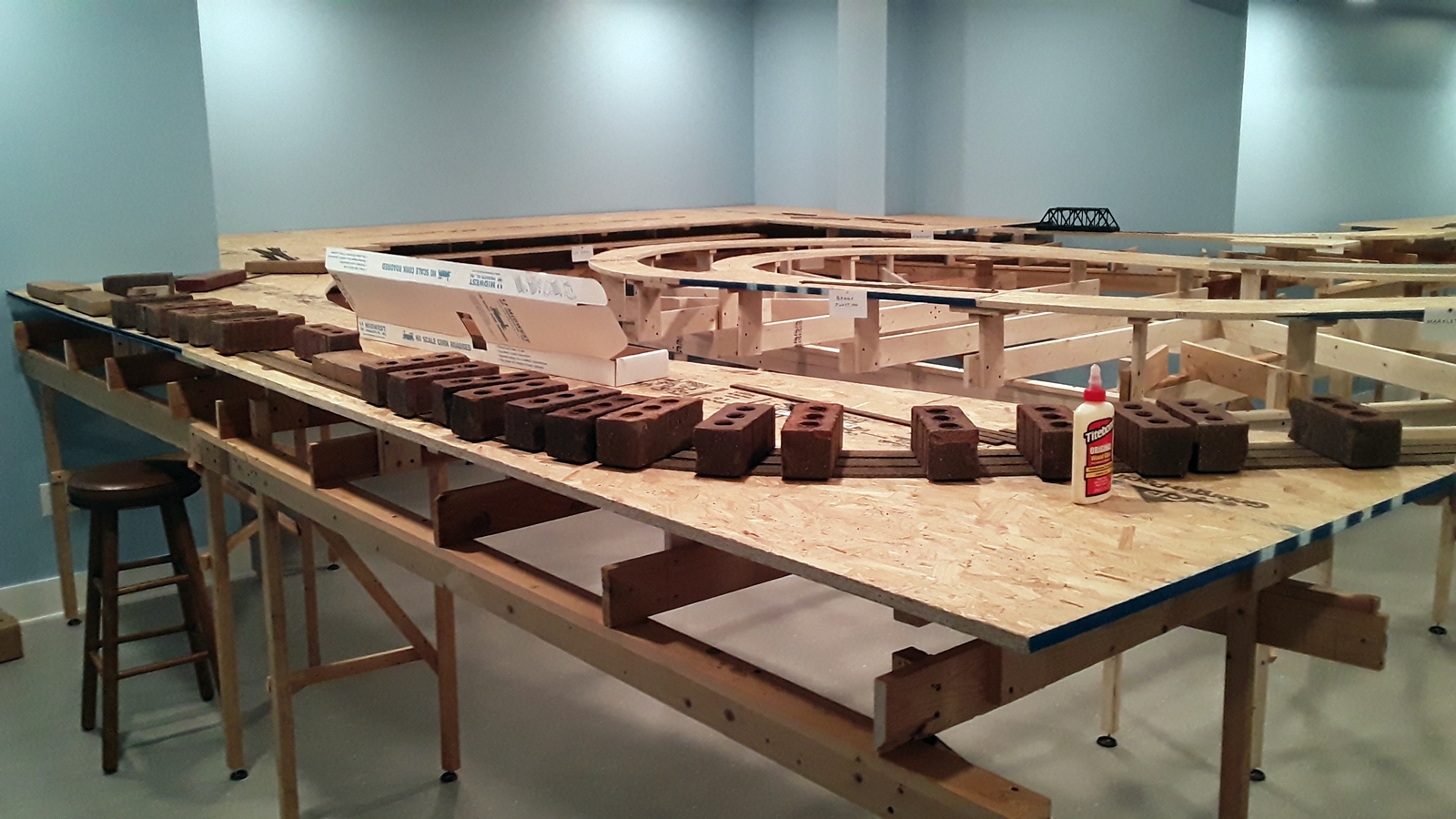
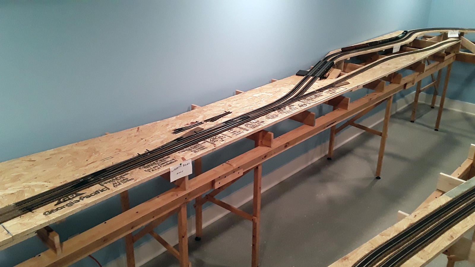
Overview of the Layout
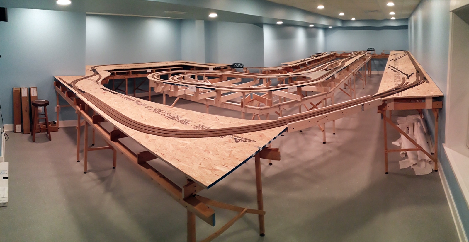
Latest view of the steel mill area.
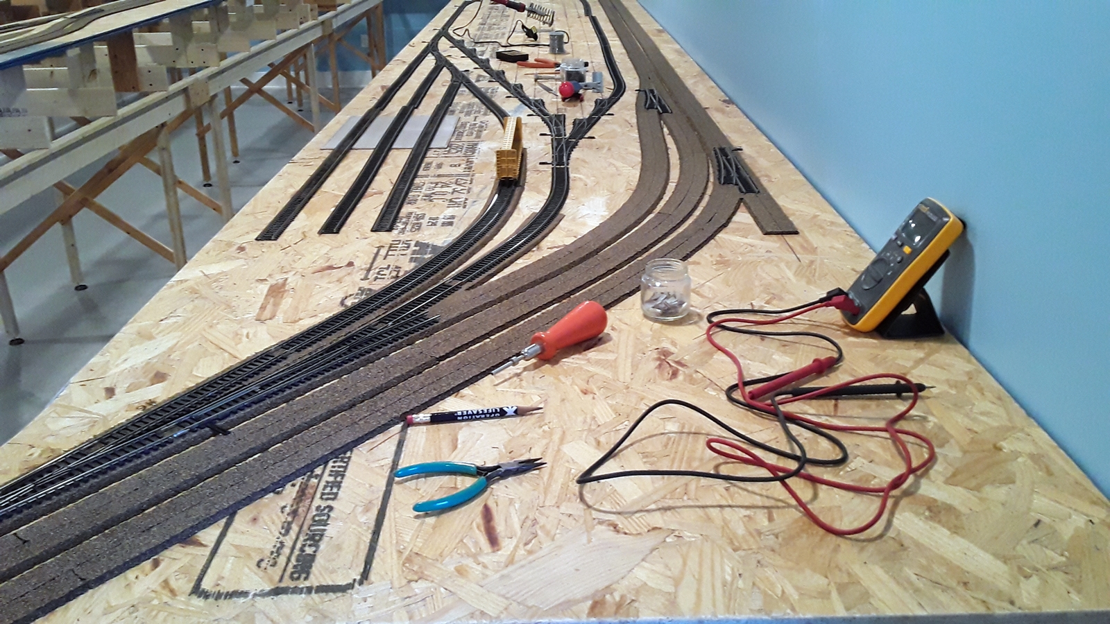
Three of the switch throws in place. I painted the ends of the handles to easily
see which direction the switch points are in.
Green: for aligned normal
Yellow: for track aligned between mainline tracks
Red: for diverging route off the main
For the background behind the steel mill, I wanted to make a large rolling mill.
It actually didn't cost much money to make - it was made out of 3/8-inch foam
board, aluminum foil for the siding, and sand paper for the roof.
All the details were parts left over from other buildings.
This is the overall view of the rolling mill. It is 99 inches long.
Added the lighting above the doors. All are LED lights.
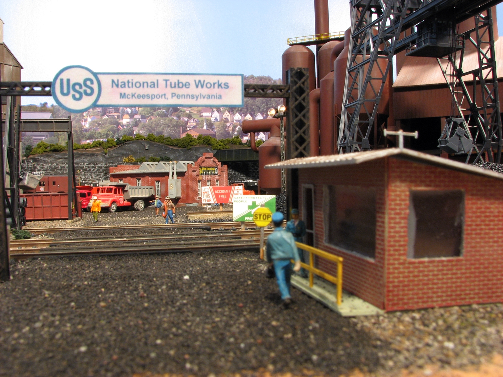
Because the mill stretches between McKeesport and Pittsburgh on the layout, I didn't want to
name it National Tube Works, or Edgar Thompson Works. I will use the more generic
United States Steel - Mon Valley Works.
The sign was taken from a photograph found online.
This view shows the background interior that shows up with the layout room lights off.
The bridge to the blast furnace over the mainline and Union Railroad tracks.
The piers are now weathered and deck girders were added to the I beams with lettering and logos.
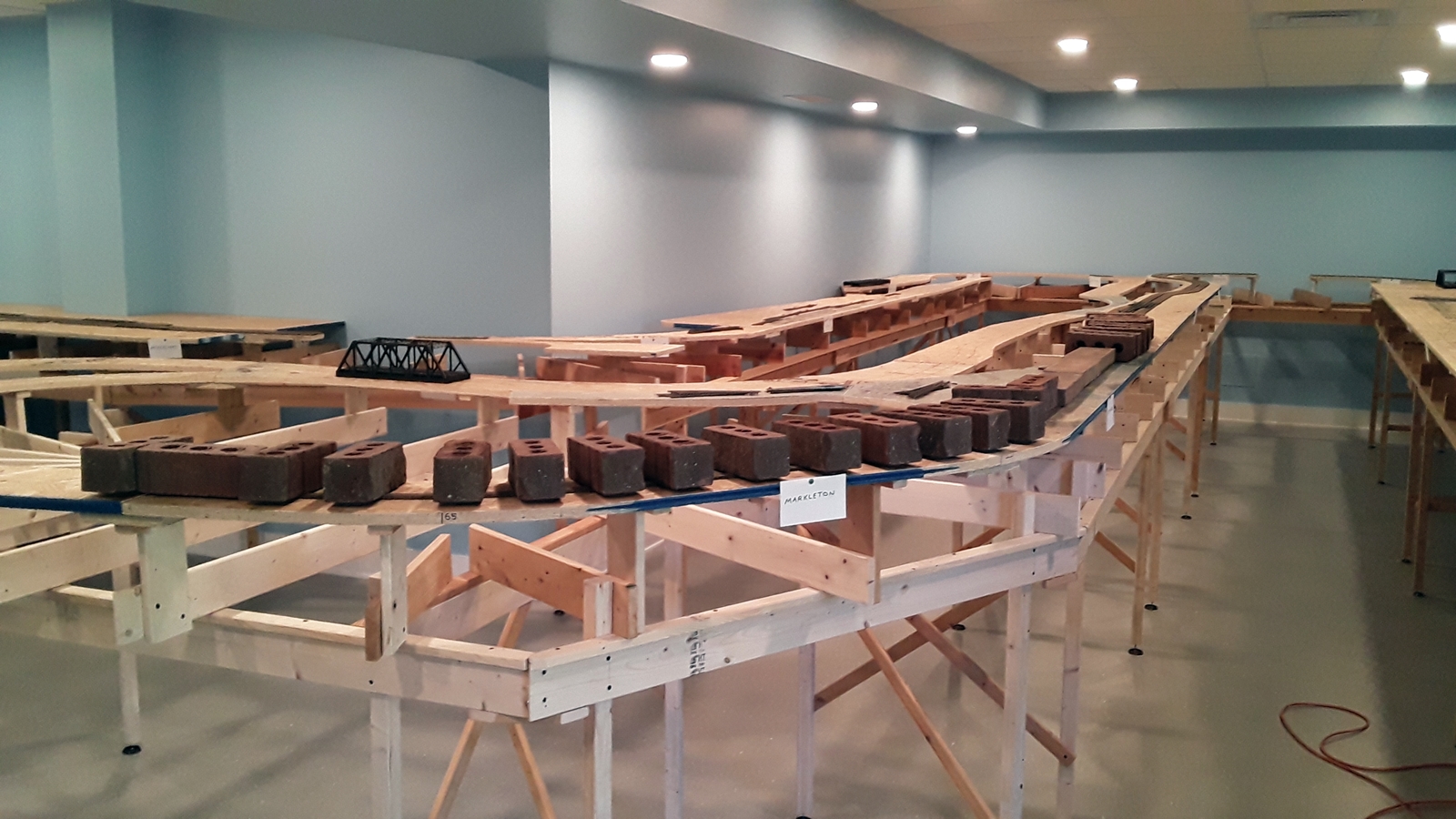
Foam board being glued in place for the wall along the Monongahela River.
The bricks are holding it in place until the glue dries.
Concrete pad in place, painted and weathered at the sanding rack.
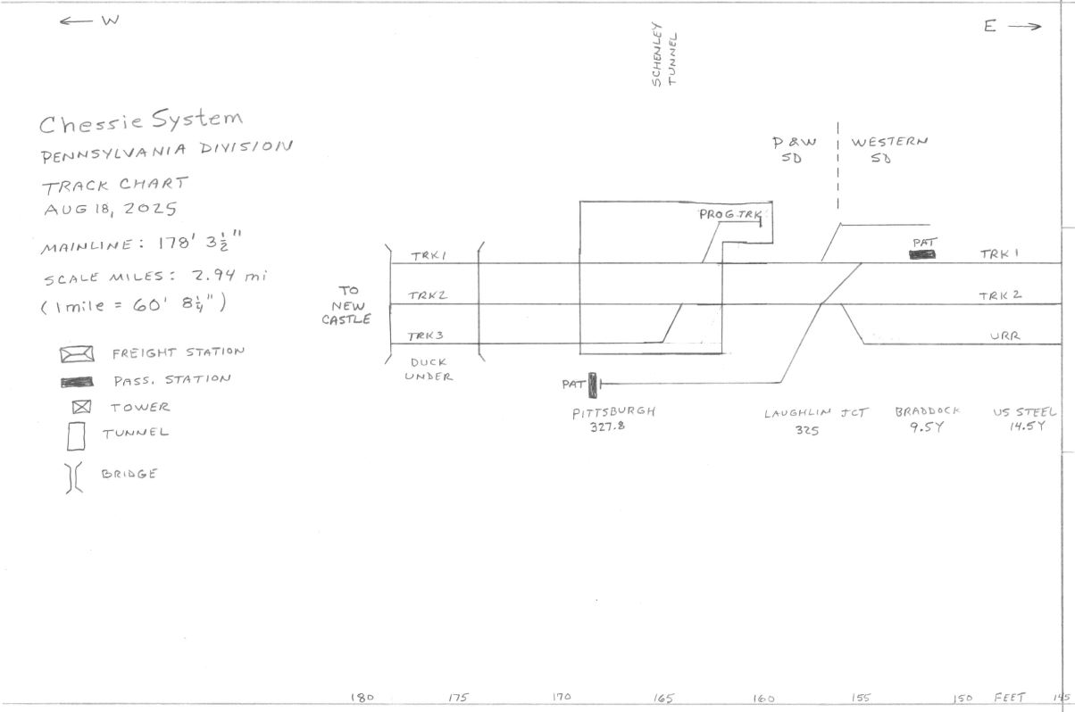
Layout Specifications:
Mainline Length:
Track 1: 177.5 ft (2.93 scale miles)
Track 2: 181.5 ft (2.99 scale miles)
Minimum Walkway Width: 35"
Minimum Subroadbed Height: 44.5"
Maximum Subroadbed Height: 48.75"
Minimum Radius: 30"
Curve Easements: 18" transition, 0.5" offset
Super Elevation: 0.030"
Atlas Code 100 Flex Track and Switches
Tangent Track Center to Center: 2"
Curved Track Center to Center 2.25"
Yard Track Center to Center: 2"
Mainline Maximum Grade: 1.5%
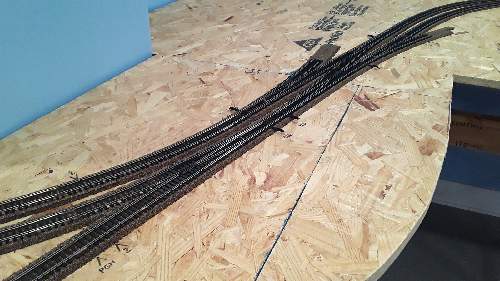
Mainline Crossovers: #8
Spurs off of the Mainline: #6
Yard/Industrial Switches: #4
DCC: NCE Powerhouse Pro System with 3 power districts
JMRI Software
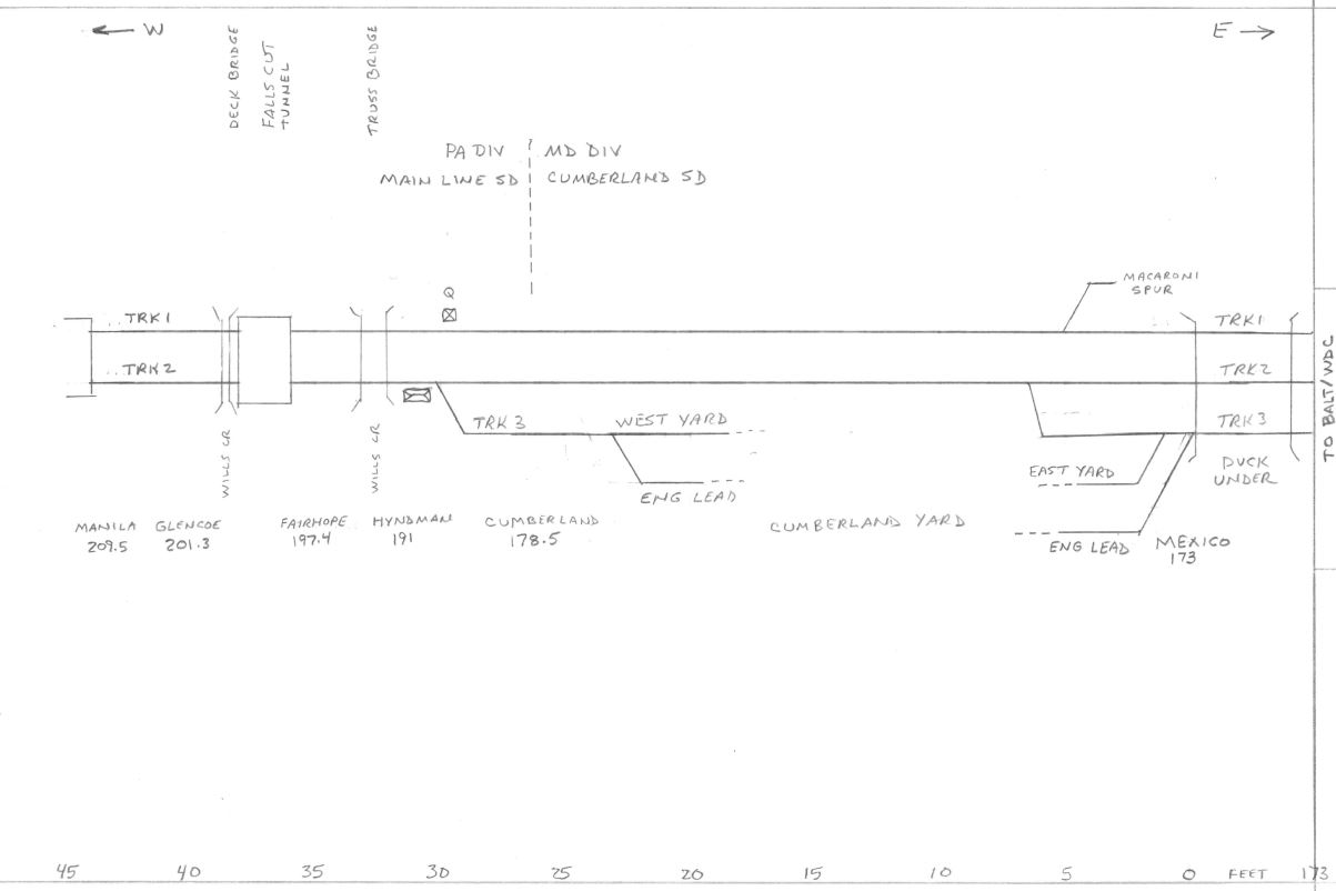
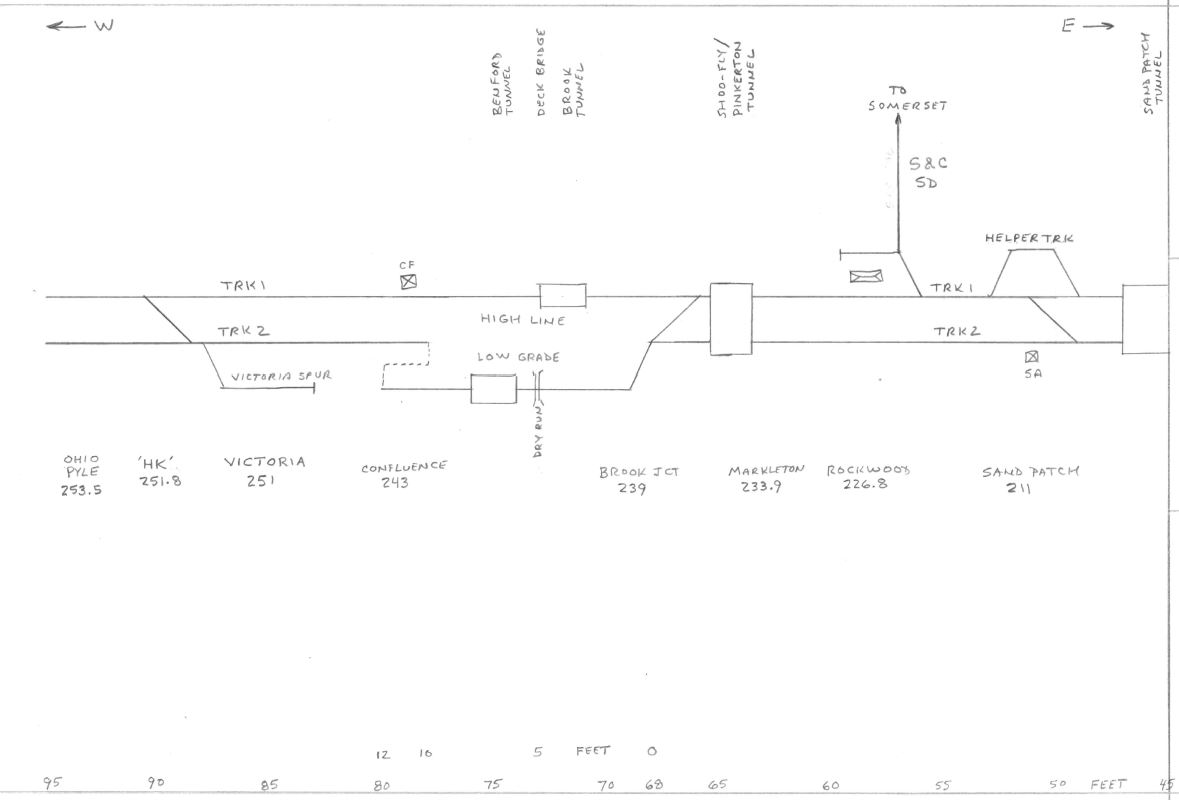
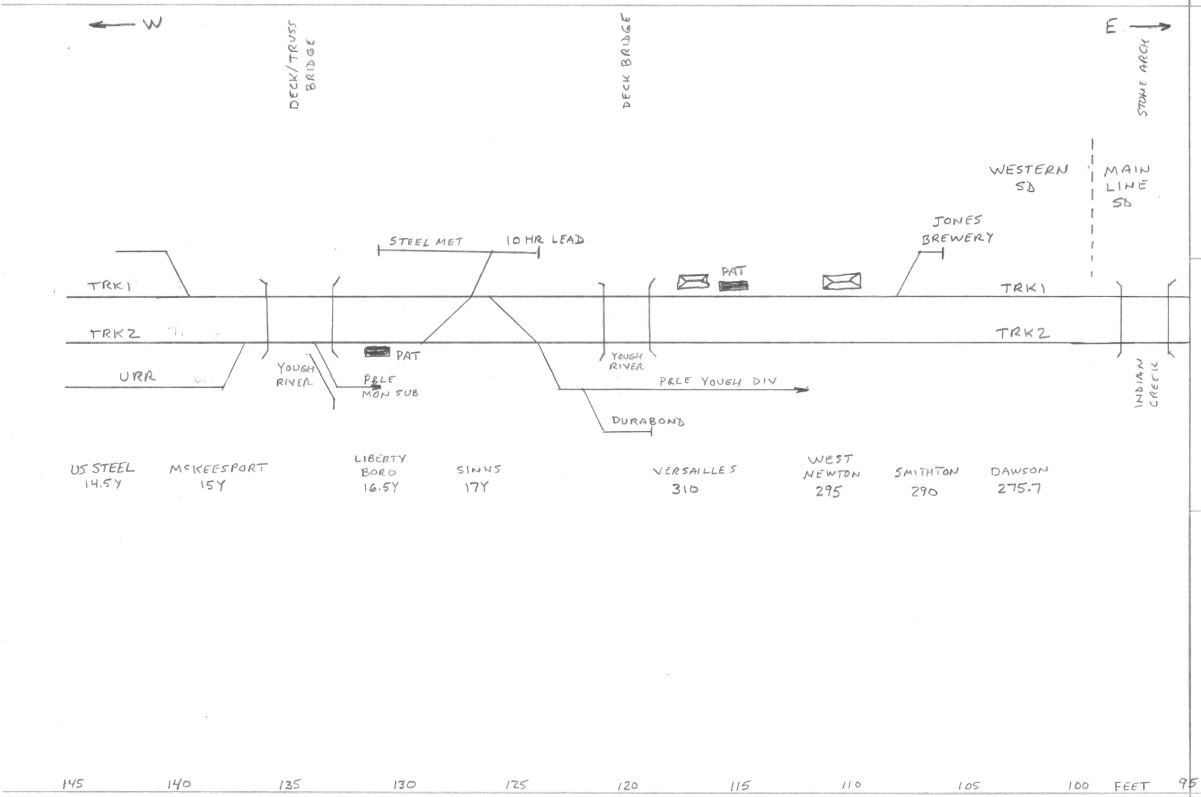
Track charts showing the location of switches, tunnels, bridges, elevation, grade, and the interlockings and blocks.
Some of the track is not totally accurate due to space, but all the tunnels and bridges are properly located.
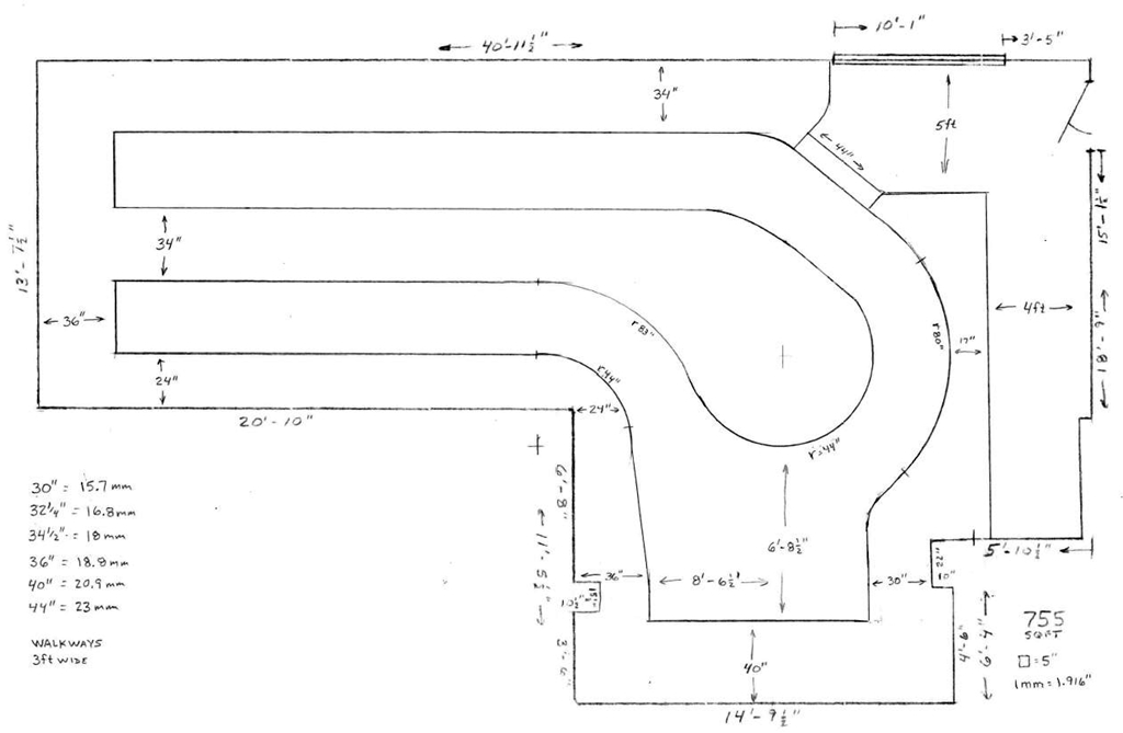
Train room dimensions along with the approximate dimensions of the layout.
The size changed a bit as I was laying out the track. The room is approximately 755 sqft.
A photo from my old layout in Maryland (2001 - 2019).
A trailer jet with 6 locomotives passes through Markleton PA along the Casselman River.
I am a member of the following railroad historical societies.

