


Early
in 2008 I was inspired by the live steam railtruck that was built by
Sonny Wizelman and which competed in the 2008 drawbar contest at
Diamondhead...and won it's division, I might add.
I started looking for 1:20.3-scale plans for an early 1900's Model-T truck as
the basis for my scratchbuild. In the August 2004 issue of Garden Railway
Magazine, a Ted Stinson plan set was included for a 1927 Model-T Oil Truck and
served as my underlying design for the Model-T
Railtruck.
I found this scaled drawing at Sidestreet Bannerworks:
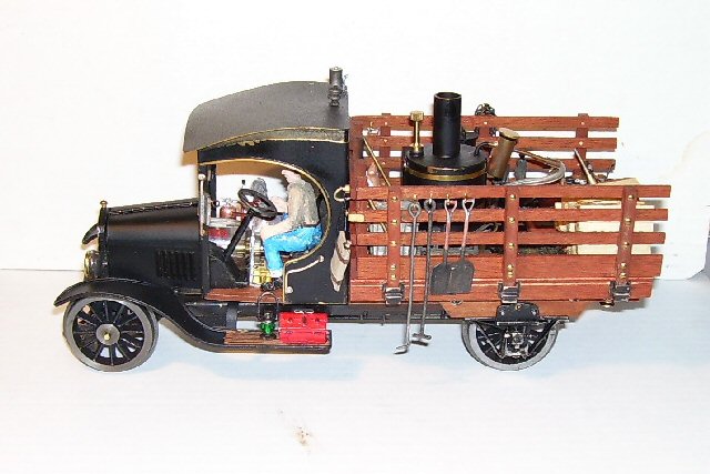
Here's the results after about 5 months of work:
And now for what it took to do this scratchbuild, see my Model-T Builder's Log on MyLargeScale.com.
I ran the Steam Powered Model-T at the Summer SteamUp in Sacramento in July 2008.
And finally the "Steam in the Garden" magazine article with an initial publication date of July 2009 in 3 parts:
Article# 1, July/August 2009
Building a Steam Powered Model-T Rail Truck
By Howard Maculsay
A 1927 Tin-Lizzy should have been so lucky
In April 2008, I was inspired by seeing “Matilda”, the live steam rail truck built by Sonny Wizelman which competed in the 2008 drawbar contest at Diamondhead...and won its division, I might add.
Since I have been modeling in Narrow gauge, I started looking for 1:20.3 scale plans for an early 1900's Model-T truck as the basis for my scratch build. In the August 2004 issue of Garden Railway Magazine, a Ted Stinson plan set was included for a 1927 Model-T Oil Truck and will be serving as my underlying design for the Model-T Rail truck. This scaled drawing is available from Sidestreet Bannerworks. I also found that Northeast Narrow Gauge (nemodel.com) makes model kits in its “Tin-Lizzy” line that has some of the more difficult parts, such as the radiator, steering wheel and headlight castings for a 1925 Model-T Stake Side Truck.

Photo 1 “1925 Model T Stake Side Truck”
More research turned up another useful picture on finescale.com

Photo 2 “L.P. Stewart & Bros.”
Although I was able to find documentation that Model-Ts were used as rail vehicles, what I want to do would certainly not be prototypical.

Photo 3 “See on Youtube www.youtube.com/watch?v=0k7YXc8G8-s” )
I want to power it with a butane-fired boiler and steam-motor, and still stay close to the 1:20.3 scale Model-T Stake Side Truck dimensions. The trick was going to be finding live steam components with the dimensions of the Model-T vehicle.
My initial searches didn't turn up any candidates until an April 2008 weekend steam up, where Sonny Wizelman graciously brought his rail truck, Matilda. It was obvious that staying within the confines of the 1:20.3 scale Model-T truck was going to be difficult, if not impossible. Major length extensions to the truck bed would be required to hold the steam components I had in mind. But, lo-and-behold, Sonny's next live steam project, a Steeple Cab switcher, required a small steam motor, boiler, and butane tank.
Sonny had acquired the steam components from a "Pepper" locomotive but had since decided on a different solution and was about to return this little German made steam motor, boiler and butane tank to Lutz Hielscher at www.hielscher-dampfmodelle.de. Size-wise, the steam components looked to be just what I was looking for, so we made a deal.
The Steam Components
Oscillating Cylinder Steam motor: 2” tall x 1” wide x 1/2” deep
40:1 integrated geared drive train w/1/2” dia. Flywheel
Piston: 3mm (1/8”) dia., stroke length 5mm (13/64”)
Integrated final drive: 2.5mm dia. used as axle.


Photo 4 Photo 5
Boiler: 56mm (2 1/8”) tall, 35mm (1 3/8”) dia. + 1 1/16” tall chimney
Water capacity 30ml
Single L-shaped flue
Burner- external blow torch aimed at the L-shaped flue
Steam outlet pipe .080” dia.
Feed-thru lubricator 5/16” dia.,13/16” tall


Photo SEQ Photo \* ARABIC 6 “Boiler & Burner” Photo SEQ Photo \* ARABIC 7 caption, “Burner attached”
Butane tank- plastic 2 3/8” long x 1 1/8” x 7/8”
Ronson type filler valve
Built-in needle valve, with on/off lever
Integrated flexible feed hose with jet attached

Photo SEQ Photo \* ARABIC 8 caption, “Butane Tank”
The steam motor has to stand directly over the rear axle, since it is integrated with the steam motor’s geared drive train. So, to get the shortest overall length for the Steam components I placed the boiler just 1/8” ahead of the steam motor. This arrangement should produce the dimensions around which everything has to be placed on the General Arrangement Drawing.

Photo SEQ Photo \* ARABIC 9 caption “Boiler, Burner, Butane Tank Assembly”
Now, “Let there be Fire”. For an initial burner test, I took the coupled butane tank, feed hose w/jet, and burner to see how the burner and gas flow controls performed. Like most needle valves, it has a very small range between all-on and all-off. I was also going to have to make bracketing to hold the spring-loaded-off valve in an “on” position when running.

Photo SEQ Photo \* ARABIC 10 caption “Burner Test”
The General Arrangement Drawing
So now that I have the steam component assembly dimensions understood I set out to make a General Arrangement Drawing with the goal to answer the question; “will it all fit”? The small steam motor, boiler, and butane tank will fit into the Model-T truck design with only a quarter inch here, Ľ” there added…for an overall extension of 3/4” in total length, and 3/8” added to the width. The planned model will be 10 ˝” long, 4 3/8” wide.

Photo SEQ Photo \* ARABIC 11 caption, “General Arrangement Drawing”)
The Under-Carriage/Frame
The basic under-carriage was made from .032" thick brass plate and ˝”x 21/64” oak for the 2 truck bed beams. Along the length of the of the brass under-carriage at the widest part, the outer Ľ” has a 90degree downward bend for strength. I used my sheet metal brake to make this bend.
I decided early-on that because the steam motor was so small that I had better use ball bearings on the axles to keep friction in the drive train to a minimum. The drive wheels [rear] will have external ball bearing journals to minimize friction. The front wheels will also have ball bearings, but the journals will be on the inside of the frame. At this point, I decided to make a 3-D general under-carriage drawing using Google’s SketchUp. I had yet to decide on what rear journals to use, since they had to have enough meat around the axle to accept the small ball bearings. So for now I just drew in a simple block journal. The motor support is shown as an integral part of the frame.

Photo SEQ Photo \* ARABIC 12 caption, “Under-Carriage & Bed Frame Beams”
The Insulation Layer & Cab/Hood Connector
I decided I had to add a 1/8" layer under the cab/hood/boiler to facilitate raising the deck beams to help clear the rear wheels. To kill 2-birds-with-1-stone, the layer is high heat circuit card material (Garolite G 10-FR4)...hence an insulation layer between burner/boiler and the rest of the brass undercarriage. Additionally, the cab & hood will be made to be connected together so that it'll lift off the undercarriage in one piece.

Photo 13 caption, “Cab/Hood Base & Insulation Layer”
The next picture shows the insulation layer mounted to the brass undercarriage using three 2-56 screws which also attach the boiler. Each of the oak deck beams are attached to the 1/8" thick insulation layer by 2-56 NBWs. The deck's oak crossbeam is escutcheon pinned and CA'd.

Photo 14 caption, “Assembled Insulation Layer”
At the front of this .015" thick brass base connector is a piece bent 90degrees vertical and shaped to fit the backside of the radiator casting.
This picture shows the wood cab floor positioned to be attached to the brass cab/hood base connector along with the front hood support soldered to the backside of the vertical radiator backing.


Photo 15 caption, “Cab/Hood Attachment” Photo 16 caption, “Front Hood Support”
At this point I went on to work out some of the initial planning for the Front Pivot Bolster Journals & Wheels, Rear Journals & wheels, and their interfaces with the brass under-carriage and the hardwood truck bed beams, basically enough planning to figure out sizing to get some ordering completed.


Photo 18 caption, “Front Pivot Bolster” Photo SEQ Photo \* ARABIC 13 caption, “Rear Bolster”
![]()
Photo 20 caption, “Frame/Truck Bed Beams”
I found miniature 2.5mm I.D x 6mm O.D. ball bearings from www.bocabearings.com and got them on order. I also ordered the 2.5mm & 6mm drill bits & reamer for making a snug home for the bearings in my journals and for drilling the wheel hubs for the 2.5mm axles. At this point, in an evolving design, I planned on using modified "Ozark Miniatures" fully sprung Journals, part#1010, but it would take quite a bit of modification to accept bearings. Then at the June 2008 Big Train Show in Ontario, CA. I picked up alternate rear journals from Ozark Miniatures.
The replacement journals are Ozark's Coil Spring Braced Journals, part# 1011.
These new journals have a larger surface surrounding the axle hole; enough to allow for counter-drilling a hole to accept the 6mm O.D. ball bearings.
Photo 21 caption “Modified Coil Spring Braced Journals”
I decided on 12-spoke wheels to match the wood-spoke wheels of the prototype Model-T and with an outside flange diameter of 1.563"
The Tin Lizzy kit arrived from NENG, so I'll be using the radiator, headlights and steering wheel castings. I got some wheel castings from Diana and Tom at Sulphur Springs. They aren't quite the size I wanted, but I'll be able to machine them to close to the size I want. They are cast iron.....this would be my first attempt at machining cast iron.
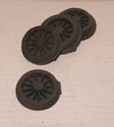
Photo 22 caption, “Cast Iron Wheel Castings”
In a future issue, we’ll move on to the Cab.
My Modeling Environment and Methodology (possible sidebar)
I & my wonderful wife Gail, do most of our modeling/crafts together in our living room. We are always playing ideas and progress off of each other…being in close proximity just makes sense for us. My larger tools are out in the garage and my small Lathe & Mill share space in a utility room.
• Disc Sander, Band Saw, Bench Grinder, Sheet Metal Brake
• Mini butane torch & other small hand tools
• Sherline Lathe & Mill
• CAD Software -eMachineShop.com, Google SketchUp
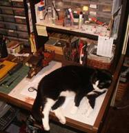
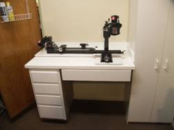
Photo 23 caption, “Living Room Photo 24 caption, “Mill & Lathe setup”
Work Space & Friend”
From my previous life in the Computer Software Development Industry, I used the credo, Plan, Plan, Plan, then Plan again. That has just carried over into my modeling. I’ve added computer aided design software from eMachineShop.com and Google SketchUp, to my bag of tools. I’ve learned to use card stock mock-ups to discover fit-check problems and to get a good perspective of how the model will look when completed. And being a novice machinist, I started out by writing out the setups and sequential machining steps to help me think through the process and to be sure of what I was doing. “Think Thrice, Measure Twice, Cut Nice” works well for me.
About the Author (sidebar)
I, like many others, started in G-scale with the train running around the base of the Christmas tree. It still took years after our two sons grew up and out on their own to get any additional G scale locomotives and rolling stock. Still it was limited to static displays around the house. After I retired, I ran head long into the live steam topic after reading a copy of the magazine of the same name. Still I was only dreaming. Once I found the G scale forums on the internet, I was off to the races. The selfless sharing of expertise and ideas was most encouraging. I started, like others, with a Ruby kit, but was intrigued with bashing the kit. Many thanks go to folks like Vance Bass and Kevin O’Connor for getting me through my first live steam kit bash project. During this time I also acquired many back issues of SitG, trying to catch up with the hobby and to gain even more ideas and inspiration.
Article #2, September/October 2009
Building a Steam Powered Model-T Rail Truck
By Howard Maculsay
A 1927 Tin-Lizzy should have been so lucky
The Cab
I made the under-carriage from .032" thick brass sheet, attached to 2 Oak deck beams [5" x 21/64" x 1/2"] using hex head screws. The truck's bed decking and cab floor will be 1/8" thick mahogany plywood scribed to represent individual planking.
The mockups of the truck's cab and hood/radiator was done by cutting-out and attaching the cab drawing to light card stock using spray adhesive. The mockups and drawing changes were repeated until all the clearances needed were met. Particular attention was paid to the clearances needed for the butane tank and burner, since they will have to fit under the hood and pass thru the cab. The cab and hood/radiator will be made as a single removable assembly. The cab is made from .015" thick brass sheet. The Cab drawing shows the positioning of the rear hood support and the wire beading that will be added along the edge of the door openings. The hood supports brass channel bent to approximate the shape of the radiator. The open side of the channel faces out so that a wire beading soldered to the hood's front & rear edges will fit into the channel.
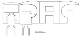
Photo SEQ Photo \* ARABIC 1 caption, “Cab Drawing”


Photo SEQ Photo \* ARABIC 2 caption, “Cab & Hood Mockup” Photo 3 caption, “Checking Burner Clearance”
I tend to use T-pins a lot for holding things in place for soldering. Here the rear hood support is being readied for soldering by pinning it to the cab's front wall using my ceramic fiber soldering pad as a base. The opening for the front windscreen is yet to be cut using my nibbler.

Photo SEQ Photo \* ARABIC 3 caption, “Hood Support Soldering”
After making the 90degree bends at the two rear corners of the cab, the cab’s right-front corner can be soldered.
Across the inside of the cab's front, I added a reinforcing strip of brass to stiffen up the top of the windscreen frame. Down each side of the windscreen, I added a length of 1/8" square brass tubing to form the 2 front corner posts.
The top of the cab sides needed some stiffening, so I added a rectangular brass piece near the top at the back. This also holds a short portion of the sides at right angles to the back wall before allowing the sides to curve in towards the narrower front wall.
Having finished the soldering on the cab, I connected the cab with the hood/cab base connector by soldering it to the bottom of the rear hood support. Onto the inside of the cab's back wall I soldered a couple of L-shaped brass pieces to secure the cab to the wood floor and in-turn to the base connector using escutcheon pins. The pins will extend down into the insulation layer as part of the cab's positioning/fastening scheme. Another pin will be used to position the front of the hood and a single 2-56 screw down through the floorboard and threaded into the brass undercarriage will secure the whole cab assembly.


Photo SEQ Photo \* ARABIC 4 caption, “Hood/Cab Base Connection” Photo SEQ Photo \* ARABIC 5 caption, “”
A quick temporary assembly of the cab with the under-carriage at this point verifies that the Butane tank fits into the hood through the front cab wall cutout and that the hose connection to the Burner is aligned and the spacing all works.
From the top view of the cab you can see 1/8” square tubing at the front corner posts.


Photo SEQ Photo \* ARABIC 6 caption, “Tank clearance” Photo SEQ Photo \* ARABIC 7 caption, “Shows Cab’s Corner Posts”
The removable roof is 2 ľ” square. I cut it from .010" thick brass sheet. The compound curve was accomplished by hand and using various diameter bottles from our refrigerator.
A mounting flange was formed and soldered in place on the underside of the cab's roof. The flange just snug-fits down inside the Cab’s top to make it easily removable.


Photo SEQ Photo \* ARABIC 8 caption, “Mounting Flange” Photo SEQ Photo \* ARABIC 9 caption, “Cab Roof Side View”
The front window is cut from a piece of microscope slide glass, 1 13/16” wide x 1”. A windscreen was fabricated to swing open from the bottom. The microscope slide glass was cut to just under the width of the cab's windscreen opening to accommodate a brass C-channel pieces on each side. The bottom of the windscreen has a piece of 3/64" dia. brass rod soldered to the side channels. At the top, in order to get a hinge effect the side channels are drilled at the top to accept a piece of 3/64" brass rod. With the end of the rods bent down at 90degrees, they insert into the top of the 1/8” square channel that forms the cab's front corner posts, making the windscreen easy to remove.

Photo SEQ Photo \* ARABIC 10 caption, “Windscreen”
The roof's underside was sprayed Hi-temp flat black while the top was sprayed with a black textured metallic coating by Dupli-Color (available at Auto Parts stores). The cab was also sprayed. All sprayed parts received a coat of Dull Coat [lacquer].

Photo SEQ Photo \* ARABIC 11 caption, “Windscreen Installed”
The Hood
I've decided to give a try at making a working hinged hood, like the real Tin-Lizzies. The hinge at the top is like a piano hinge, design-wise.

Photo SEQ Photo \* ARABIC 12 caption, “L.P. Stewart & Bro. Prototype”

Photo SEQ Photo \* ARABIC 13 caption, “Hood Drawing & Hood Supports”
Here's my first attempt at a hinge. It'll take 3 hinges. I got instructions for making hinges from a book recommended by Vance Bass, “The Complete Metalsmith” by Tim McCreight. Thanks Vance.

Photo SEQ Photo \* ARABIC 14 caption, “Practice Hood Hinge”
The hood is made with 4 pieces of .010 brass sheet, some .0625” dia. copper tubing for hinges, and brass wire for hinge pins to fit inside the copper tubing.
The hinge at the top of the hood is a full piano type hinge since it’s visible.
Using my patterns spray glued on the brass sheet, I used my nibbler to cut the “teeth” in both the left & right sides of the top hinge. I carefully soldered a piece of copper tube along the top hinge’s fold line with the teeth of the 2 hood halves intermeshed. Here where the trick to make ultra thin pieces of solder is key to not getting solder to flow beyond the each individual tooth. Careful application of flux also limits the flow of solder into places not wanted. I used a small pencil-sized torch to apply heat to all the surfaces involved.


Photo SEQ Photo \* ARABIC 15 caption, “Ready for the Nibbler” Photo SEQ Photo \* ARABIC 16 caption, “Teeth cut”
The side hinges are somewhat simpler, a single hinge point at each end of the hood and one in the middle. The side hinge is not visible from the outside of the hood.

Photo SEQ Photo \* ARABIC 17 caption, “Simple Side Hinge”
After some minor cleanup, a careful cut through the copper tube between each adjacent tooth yields a working hinge when a piece of thin brass wire is inserted down through the adjoining copper tube segments.
The top hinge pin extends slightly into the cab’s front wall and radiator’s backing plate through holes drilled at the center-top location of the hood.
It’s obvious at this point, there’s something missing….the louvers. There will be more information on Louvers in a later installment of this article.


Photo SEQ Photo \* ARABIC 18 caption, “Closed Hood” Photo SEQ Photo \* ARABIC 19 caption, “Opened Hood”
The Butane Filler & Flow Controls
I placed a slot in the radiator backing plate that will allow for filling the butane tank through the Radiator Casting without having to remove the tank from its tight space. Filling the tank then becomes a cinch.


Photo SEQ Photo \* ARABIC 20 caption, “Slot for Filling” Photo SEQ Photo \* ARABIC 21 caption, “Filling the Tank”
I made an aluminum bracket to hold the butane tank in place. A single
2-56 screw, threaded into the brass under-carriage holds both the butane
tank and the cab in place. On the same mounting screw there is a brass
bracket with a notch which serves to hold the gas on/off valve in the “on”
position.
The control over the amount of butane flow is built-in to the tank, but it is hard to reach in this cramped space. I added a short round lever to the gas control valve.


Photo SEQ Photo \* ARABIC 22 caption, “Tank Bracket” Photo SEQ Photo \* ARABIC 23 caption, “Flow Control Lever”
The Radiator Casting
The white metal radiator casting from NENG (Northeast Narrow Gauge, Ted Stinson) will be attached to the front of the Hood/Cab Base Connector’s vertical backing plate using epoxy.
For the radiator, a 9/64” hole was drilled matching the backing plates slot to facilitate butane refills.
At the top of the radiator, a small eyelet and short escutcheon pin simulates the radiator cap. Near the bottom of the radiator casting a hole for the starter crank was made. The crank was made from a 1/16” x 1” escutcheon pin and a short piece of brass tubing for the handle. Another short piece of brass tubing is extended through the hole in the radiator casting and CA’d in place. The crank is inserted into the tube and the end of the escutcheon pin is bent over to allow for rotation.

Photo SEQ Photo \* ARABIC 24 caption, “Radiator Casting”
The Truck Bed, Stakes & Rails
I produced a rear deck, stake & rails drawing and did a fit check prior to cutting and assembly.

Photo SEQ Photo \* ARABIC 25 caption, “Truck Bed, Stakes & Rails Drawing”
The rear truck bed's top surface (5 1/8 “long, 5 3/8” wide) is made from laser-scribed hardwood plywood, while the edge boards are 3/32" thick mahogany and CA’d in place. The side stakes are 5/32" square x 1 15/16” tall hardwood and rails are 3/32" thick mahogany. The front stakes are 5/32” square x 1 5/8” tall.
Using the full size drawing as a template, the stakes and rails are T-pinned in place and escutcheon pinned and CA'd. The bed has a cut out to clear the burner, boiler & steam motor.


Photo SEQ Photo \* ARABIC 26 caption, “Truck Bed” Photo SEQ Photo \* ARABIC 27 caption, “Front & Side Stakes with Rails”
While the front stakes and rails are physical attached to the bed and supported by 45degree brass rods down to the truck bed, the side stakes and rails are held in place by the stake pockets and consequently removable. The stake pockets are Ozark Miniatures #1001.


Photo SEQ Photo \* ARABIC 28 caption, “Stakes & Rails Attached to Bed” Photo SEQ Photo \* ARABIC 29 caption, “Test Fit”
The Boiler Cladding & Lagging
Adding a boiler heat shield is necessary to protect the wood surfaces near the boiler. I used the drum sander on my drill press to create some additional space between the boiler and the truck's wood bed beams/decking.

Photo SEQ Photo \* ARABIC 30 caption, “Bed ready for Cladding”
I then added a brass heat shield/radiator between the boiler and beams/decking. I soldered a ring of 1/16” brass rod to the top edge of the heat shield to provide some rigidity since openings in the shield were needed for the burner and for the steam motor mount. In between the brass heat shield and the boiler are 2 layers of hi-temp gasket material surrounding 2 layers of ceramic boiler insulation.


Photo SEQ Photo \* ARABIC 31 caption, “Brass Cladding” Photo SEQ Photo \* ARABIC 32 caption, “Sandwiched Lagging”
The Wheels
The wheels are cast iron castings from Sulphur Spring Steam Models HLP-W41
I've been using a 1:20.3 scale model as a basis for this build. To maintain a correct Model-T spoked wheel profile, I've patterned them as close to the scale model's wheels, as possible. Even though the casting is a little larger than desired, I'll was able to machine it to about the right size.
The dimensions for the wheel drawing:
Outside dimension at flange 1.720".
Front rim at tire 1.531" dia.
Tire surface angle 2.5%
Wheel thickness (excluding hubs) .250"
Flange thickness at base .086"
Front axle hub .063" high x .3750" dia. (as is)
Rear axle hub .1250" high x .498" dia.


Photo SEQ Photo \* ARABIC 33 caption, “Wheel Drawing” Photo SEQ Photo \* ARABIC 34 caption, “Scale Model vs. Casting”
The casting was chucked up in my 3-jaw chuck on the treads on the casting's front side. The backside was faced-off. The backside was further machined to form the rear axle hub at .498" dia. x .1563" deep and then to reveal the spokes. The thickness of the wheel at this point was .250”. The back side of the spoke portion were further recessed another .0469”. The outside rim's [flange] flash was cleaned up to a rough diameter of 1.750" since the chuck jaws were too close to machine to the final diameter.
Without the work piece being removed from the chuck, a 3/32" [.0938”] diameter hole was drilled thru the hub and then reamed to the final axle diameter of 2.5mm (.0984“).

Photo SEQ Photo \* ARABIC 35 caption, “Turning the Backside” Photo SEQ Photo \* ARABIC 36 caption, “Finished Backside”
The casting was then reversed and chucked up on the newly turned rear axle hub. I liked the look of the raw casting’s surface, so I left the front of the spokes and hub as is.
The front axle hub’s diameter was left as is. The outside rim (flange) was turned to its final diameter at 1.720".
Now I was ready for the 2.5 degree taper machining of the wheel's tire. Again, without removing the work piece from the chuck, I setup my compound slide and set the taper to be 2.5 degrees and turned down the tires surface until the outside diameter of the front rim edge was 1.531" and leaving the flange .086” thick at its base.
Photo SEQ Photo \* ARABIC 37 caption, “Finished Frontside”
And finally, for the side-by-side comparison. The 1:20.3 model wheel is only .002” smaller than the tread of the machined casting. I’m satisfied!!

Photo SEQ Photo \* ARABIC 38 caption, “Model Wheel vs. Machined Casting”
The Rear Journals
The rear journals can now finally be fitted based on the finished wheel dimensions.
A 1/8” x 17/32” x 3” mahogany spacer is needed to provide adequate positioning of the journals, both for wheel width & distance of axle below the truck’s bed beams. For a mechanical connection, the coil spring braced journals (Ozark part# 1011) have been modified by removing the center, cast-in NBW, and replacing it with a 0-80 hex head screw with its washer & nut facing out in addition to using CA between the spacer and the journal.

Photo SEQ Photo \* ARABIC 39 caption, “Journal with Spacer”
In order not to have the truck sitting too high over the rails, some relief had to be cut into the bottom edge of each deck beam to accommodate the curve of the wheel & flange. I again used a sanding drum on my drill press to make this recess.

Photo SEQ Photo \* ARABIC 40 caption, “Frame Beam Relief”
During the fitting, it became apparent that more space was needed between the wheels to get 1.740” between the flanges to fit the track. The depth of each wheel’s outside hub was reduced accordingly. The journals were chemically blackened at this point. The wheels are secured to the axle with Loctite Threadlocker Hi-strength 271 Red.
The Front Pivot Bolster & Journal
The front Journal/Bolster drawings were updated with later ideas on pivot points and self-centering.


Photo SEQ Photo \* ARABIC 41 caption, “Journal/Bolster Top View” Photo SEQ Photo \* ARABIC 42 caption, “Front View”

Photo SEQ Photo \* ARABIC 43 caption, “Axle/Bearing Detail”
The 2.399” long front axle is 3/16” brass rod with .624” at each end turned down to 2.5mm to accept the inside diameter of the ball bearings and wheels.

Photo SEQ Photo \* ARABIC 44 caption, “Turned Axle”
The bolster and journal frame is machined from a single piece of aluminum bar to its finished size of 1.300” long x .469” wide x .694” high. A 6mm hole is drilled though the length for the axle and to accept 6mm outside diameter of the bearings. The center .0885” section of the aluminum is machined to a depth of .504” to form a rectangular U-shape. At the center of the top section a pivot hole is drilled for a 2-56 socket head cap screw, but forward of the axle. A nut has been soldered to the top of the undercarriage at the pivot point just under the radiator casting. Between the bolster and the undercarriage is a .250” dia. Nylon washer.


Photo SEQ Photo \* ARABIC 45 caption, “Machined Journal/Bolster” Photo SEQ Photo \* ARABIC 46 caption, “Axle Installed”
The swing arm is 1/16” brass rod that is CA’d into holes drilled into the aft side of the bolster. Since making the drawing for the self-centering mechanism, I was convinced by others that I was probably over-doing it. I replaced the piano wire spring mechanism with a small, simple silicone rubber band. I placed a 2-56 threaded hole into the brass under-carriage aft of the swing arm to anchor one end of the silicone band with a screw, the other end attached to the swing arm.

Photo SEQ Photo \* ARABIC 47 caption, “Swing Arm Installed”
Like the rear wheels, the front wheels are attached to the axle hubs using Loctite.
“How about a cow catcher”, someone at the 2008 Summer SteamUp said. Luckily, the Brandbright folks from the UK were attending and selling their wares.
After looking at the cow catcher, I decided that it had a closed up look, not like the cow catchers I’ve seen. The entire bottom was a solid piece of brass joining the vertical ribs so that one could not see down to the tracks. So I used my vertical mill to remove the solid bottom portion, opening up the bottoms of the vertical ribs and then chemically blackened it.


Photo 48 caption, “Wheels & Cow Catcher“ Photo SEQ Photo \* ARABIC 48 caption, “Cow Catcher Machined”
Well, that’s all for now. Next we’ll cover the last of the major fabrication steps and the finishing touches.
Article# 3, November/December 2009
Building a Steam Powered Model-T Rail Truck
By Howard Maculsay
A 1927 Tin-Lizzy should have been so lucky
The Finishing Touches
The Fenders & Running Boards
The fender/running boards pattern acquired with the NENG model were modified to accommodate the increased length and width of the Cab and Hood. The patterns were glued to a light card stock for the fit check, along with the mechanical fittings for installing it all to the under carriage.

Photo SEQ Photo \* ARABIC 1 caption, “Fender Pattern”
Once the fitting was done & adjustments made to the pattern, the fenders/running boards were cut from .015” thick brass sheet.
A brass beading (3/64” dia. rod) was formed to the pattern. Once the pattern was removed, the beading was soldered around the edge of the fender/running board and cleaned up with a file.


Photo SEQ Photo \* ARABIC 2 caption, “Forming the Bead” Photo SEQ Photo \* ARABIC 3 caption, “Soldering the Bead”

Photo SEQ Photo \* ARABIC 4 caption, “Cleaned Up Fender”
The fender shaping was done by hand using various cylindrical shapes found the house.

Photo SEQ Photo \* ARABIC 5 caption, “Formed Fender”
A layer of Mahogany Veneer Edging by Woodtape was added for the running board after scoring the length of it to simulate boards.
The attachment fittings were formed in a way to place the running boards in line with the axles. The ends of the fittings were slipped between the Insulation layer and the under-carriage. The existing screws were sufficient to hold the fenders/running boards in place.

Photo SEQ Photo \* ARABIC 6 caption, “Simulated Wood Running Boards”


Photo SEQ Photo \* ARABIC 7 caption, “Fenders Fit Check” Photo SEQ Photo \* ARABIC 8 caption, “Fenders Painted”
A note at this point: the quarter panels shown on the pattern, between the fenders and the hood base could not be used. To fit the 45mm track, the axle length is quite a bit narrower than the 1:20.3 models axle length. Consequently, any use of quarter panels was not possible.
Forming the Hood Louvers
I got a lot of help on making louvers from my fellow modelers. But all were short of actually putting louvers in the Hood. More like, “paint them on.” I didn’t take the easy way out,
Here I’m documenting the design, building & testing of a dedicated piece of hard tooling used for making the hood louvers---another first-time-ever activity for me. It’s probably not very helpful to anyone else, since it’s unique to the Model-T Rail Truck project. I’m after repeatability here, so that’s why I’m making this tooling. There’s always a possibility that I will need to make another set of hood louvers or for that matter, another rail truck. Anyway, here is a picture of the prototype hood louvers I’m going for.

Photo SEQ Photo \* ARABIC 9 caption, “Target Louvers”
The louver forming tool is made up of 6 pieces. The tool itself is 3/32” x ˝” oil hardened flat steel stock while the base/die & its retainer/stop, the tool holder & its retainer and the side alignment stop pieces are all aluminum. Here are the plans I’m using:

Photo SEQ Photo \* ARABIC 10 caption, “Drawing”
At this point the aluminum pieces have been rough cut, faced-off to size, marked up with Dykem blue layout marker and ready for laying out the drilling positions. I’ve also cut 3 copies of the steel tool, so I can experiment with the louver’s possible end shapes and whether I’m going to use the tool strictly as a forming tool by precutting slots through the brass louver material or to use the tool as a punch by sharpening & hardening/tempering the tool so that it can be used to punch thru the brass.

Photo SEQ Photo \* ARABIC 11 caption, “Parts ready for Drilling & Machining”
The aluminum for the base/die is 1.5” x 1.5” x 2.5”. It has a side alignment stop secured to the base/die by 2- 4-40 x 3/8 socket head cap screws.

Photo SEQ Photo \* ARABIC 12 caption, “Side Alignment Stop”
The die portion is for a single louver shape is ˝” long by 3/32” wide. The die is machined into the edge of the base piece at a 30degree angle. It creates a louver that protrudes at a 30egree angle from the flat hood surface. Because of the narrow width of each louver (3/32”) a work piece retainer (1.250” x 1.5”) is secured with 4- 4-40 x 3/8 socket head cap screws across the face of the die to keep the formed brass in line with the front edge of the die.

Photo SEQ Photo \* ARABIC 13 caption, “Work Piece Retainer”
It also aligns the front face of the base/die with the front face of the tool holder.

Photo SEQ Photo \* ARABIC 14 caption, “Front Face Alignment”
The tool holder is aluminum 1.5” x 1.5” x1.0”. It has a slot milled on its front face to match the width & depth of the actual forming tool.
Photo SEQ Photo \* ARABIC 15 caption, “Slot Milled for Forming Tool”
A 1” x 1.5” retainer bar is screwed across the front of the tool body’s milled slot giving a repeatable movement of the tool against the die. Again 4- 4-40 x 3/8 socket head cap screws were used.

Photo SEQ Photo \* ARABIC 16 caption, “Retainer Bar”
The 1/2” wide x 3/32” thick steel tool itself is machined at a 30degree angle on one end in addition to being ground at a compound angle at the top & bottom edges, yielding the shape of the louver and its edges.


Photo SEQ Photo \* ARABIC 17 caption, “Steel Tool” Photo SEQ Photo \* ARABIC 18 caption, “Steel Tool”
The tool holder’s bottom face is secured to the base/die’s top face by 4- 10-32 x 1 Ľ socket head cap screws. The screws provide for firmly holding the work piece in place while forming a louver. Loosening the screws allows for advancing the work piece to the next louver position. I added a scribed reference line along the length of the base/die to facilitate side-to-side alignment of the work piece when advancing it to the next louver position.

Photo SEQ Photo \* ARABIC 19 caption, “Completed Forming Tool”
The die represents the outside shape of a louver while the tool is shaped to be the inside shape. Using a hammer to hit against the top of the tool, the brass work piece is formed into the shape of the die.
The next step was to
precisely precut slots in a test piece with my mill, using .015” thick brass
like the actual hood side pieces. I did a 6 louver test to see how
repeatable and uniform the results would be.
For the test I needed to cut 6 slots, ˝” long every .134” across the face of
the test piece. To do this, I mounted my .012” thick x 1 ˝”
dia. slitting saw blade/mandrel in my mill. I
mounted the brass test piece to a wood block and CA’d
it in place; then mounted it in my mill’s vise. To get the ˝” long slot, I
laid out a ˝” long chord on the face of my slitting saw blade. The distance
from the center of the chord to the edge of the blade was measured at .047”.
Then by advancing the x-axis .047” the blade would plunge into the brass and
wood block, producing a ˝” long slot. Now I could advance the z-axis .134”
to position the blade for the next slot, and so on. Here’s the saw setup:

Photo SEQ Photo \* ARABIC 20 caption, “Slitting Saw Cutting Slots”
With the slots so accurately cut, by removing the tool retainer, aligning the tool with the next slot was very precise. After running the test piece through the forming tool process for each of the 6 louvers I got the following:
Photo SEQ Photo \* ARABIC 21 caption, “Test result”
This produced an acceptable set of louvers, but I’m going to reduce the space between each louver from .134” to .118” (about 1/64” closer together). So I repeated the process for the real hood’s side pieces. Here’s one of the hood side pieces completed & the other being setup In the forming tool with 4 of the 6 louvers completed.

Photo SEQ Photo \* ARABIC 22 caption, “Forming in Process”
After some sharp edge clean-up of the formed louvers with a file I reassembled them with the rest of the hood.


Photo SEQ Photo \* ARABIC 23 caption, “Reassembled Hood” Photo SEQ Photo \* ARABIC 24 caption, “Hood Placed on Truck”
The Cab Interior


The Exterior Details


An Initial Firing on the Blocks
Along the way the urge to see something running became
overwhelming. So when I got to the point that the steam components
were installed I gave in and put what I had to the test.
I filled the butane tank to just below its outlet
tube (a little more than half with the tank mounted horizontal). I added the
recommended 30ml of distilled water to the boiler. It took less than 4
minutes to get a good head of steam. I flicked the flywheel in the correct
direction a few times and off it took. It sounds like a bumblebee. It ran
for a full 15 minutes as advertised, but that was not under any load, so it
might not get 15 minutes when on the track. The boiler cladding worked
well…I was able to touch the boiler cladding with little discomfort. When it
stopped running, it still had 2ml of water, the lubricator was mostly empty,
but only about ˝ of the butane was consumed, so the water will have to be
watched closely.
In the next test, I counted the drive wheel’s revolutions per minute to
calculate how fast it will travel down the track. The main drive wheels
turned at 135RPM. With a wheel diameter of 1.531” x
3.1416 = 603” in 1 min. or about 50 feet/minute. In 1:20.3 scale
speed, that’s about 11.8 mph
All-in-all a successful test…I was very pleased.

Static Run on Rollers
Running the Model-T on the rollers yielded similar results seen when run up on blocks. The main differences were that the drive wheels were now attached to the drive axle with Permatex Thread Sealant, the steam motor had to overcome any resistance of the rollers and full weight of the rail truck was being exerted on the wheels. Here you can see the flame shooting into the L-shaped flue on the front side of the boiler. Applying some manual resistance to the wheels rotation only slowed the RPMs down slightly, so I’m anticipating that it will indeed get around the track quite nicely. Next is the tryout on my track.

Test Run on Track
I got one run of the rail
truck at night, but we had some thunderstorms run though here with their
accompanying downpours so I had to quit.
Now it’s the next day and I just made a couple of successful runs around my
test track. The rail truck ran well and took my tracks slight grade better
than my stock Ruby did initially. Overall, I’m very satisfied on how it ran.

First Public Outing
Earlier in the build cycle I had agreed to make a presentation on the building of rail truck at the National Summer Steam Up in Sacramento, CA, July 2008. This was the first time I attended NSS, so besides making the presentation I was like a “kid-in-the-candy-shop”….so much to take in, so little time.

Final Builder’s Pictures


