


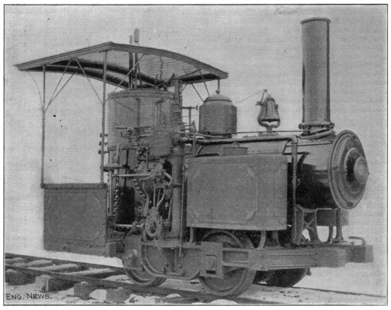
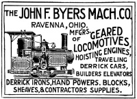
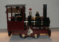
I put myself on the waitlist for this little live steam logging locomotive, called the Cricket. The first picture shows one of the 4 or 5 ever built of the prototype locomotive as it existed in the 1890s, manufactured by Byers as shown in the Byer's Company advertisement.
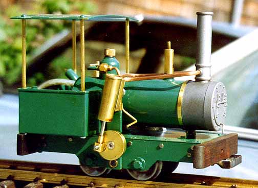
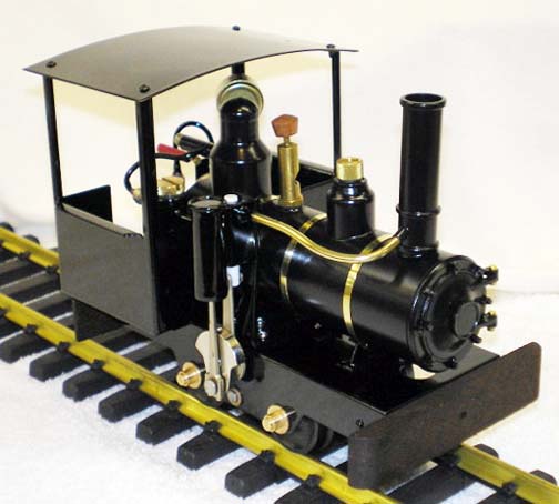
This next picture shows the cricket as originally manufactured by Berkely Locomotive Works in 1900-1994 (130 units) and the last picture shows the model as it is currently being manufactured today. I got #12 out of only 45 being built by Westminster Locomotive Works and also on the list for #37.
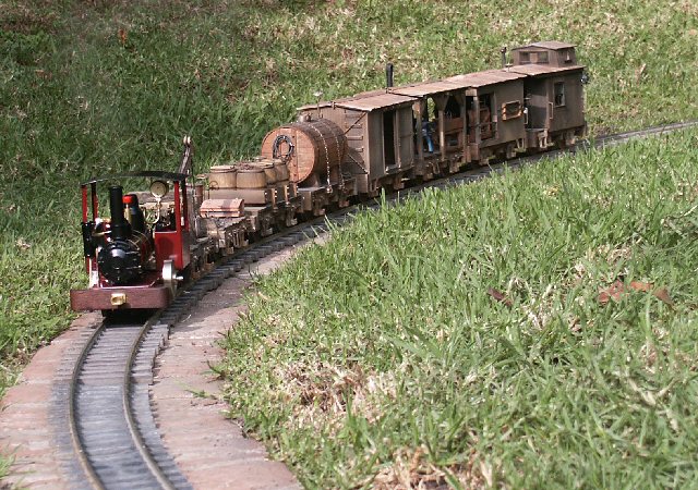
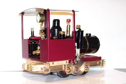
Here's my little beauty, and hard at work pulling my 12+lbs. work train consist.
These links to MyLargeScale.com show the particulars of this locomotive's history, both the prototype and the manufactured G-Scale models, plus my delivered Cricket.
Cricket Update on the first delivery
And finally, my 2009 Upgrade to the Cricket to more represent the original Byers engine.
A Mark II Cricket Looking for Its Ancestry
By Howard Maculsay
An Attempt to Mimic the John F. Byers Geared Locomotive
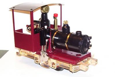
In November 2007, I took delivery of my Cricket Mark II, WLW #12, built by Mike Krionderis of Westminster Locomotive Works http://www.cricketlivesteammotor.com It has run like the champ it is, and I’ve enjoyed running it this past year and a half, but now I’m going to make some modifications to more simulate the look of the original John F. Byers Geared Locomotive.
I’ll be using an original Byers Mach. Co. advertisement, an old picture of this little engine to identify tank and side frame details and an elevation drawing found on the Geared Steam Locomotive Works at http://www.gearedsteam.com
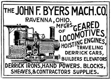
Photo# 1 “Advertisement appearing in Engineering News"- January 6, 1896”

Photo# 2 “Engineering News May 21, 1896”
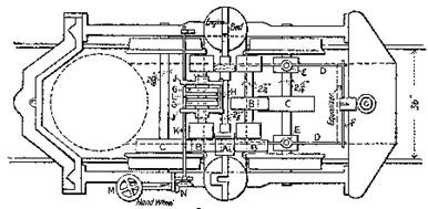
Photo#3 “Overhead Elevation Dwg. from Geared Steam Locomotive Works”
The Plan
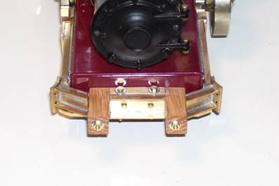
I plan to add a fabricated brass facing on the sides of the Cricket’s existing under-carriage to represent the old engines cast iron frame, a new matching front buffer assembly and a new rear end beam & coupler. The side frame facing will extend under the cab structure to the rear end beam. A short oak beam will be placed between the new side frame and the cab floor. The front buffer will feature 2 forward-protruding oak beams held in place by a pair of truss rods terminated at the front of each side frame. The rear end beam will have matching rear-protruding oak beams. In addition, I will construct a pair of non-functional brass side tanks. The side tanks, along with the existing cab’s sides and back will get a matching scrollwork decoration. The scrollwork is gold colored vinyl transfers acquired from Del Tapparo of G-Scale Graphics directly from my CAD software’s .dxf export file. http://1stclass.mylargescale.com/DelTapparo/index.htm
Del is extremely helpful and it was a pleasure doing business with him. And lastly, I will be hiding the top and sides of the existing under-carriage, so that only the new side frames will show. To do this, I will add deck beams made from Poplar.
Constructing the Side Beams & Front Buffer
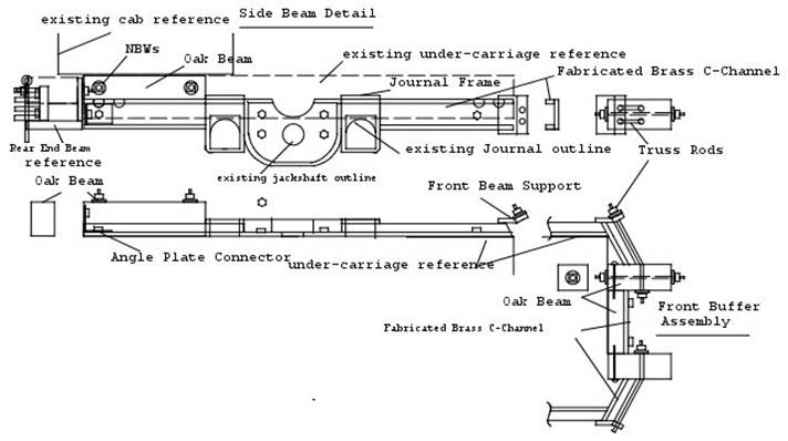
Photo# 4 “Side Beam Detail & Front Buffer Dwg.”
The critical dimensions for the side beams are the clearance holes for the 2 existing journals, the jackshaft and 4 existing under-carriage frame rivets. The center section thickness can not interfere with the crankshaft on the one side and the flywheel on the other. The half-round cutout at the top of the center section is made to clear the concentric on the crankshaft. Other than that, the rest of side beam is merely a facade.
Using an actual size drawing printout mounted with artist’s adhesive, I did the brass cutting using either my hand nibbler or my drill motor powered “Rodman” Nibbler.
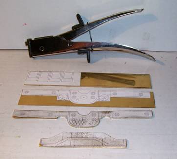
Photo# 5 “Using Patterns to Guide Cutting”
The side beams are 6.305” long x .4375” wide with the center section at 1.430” wide x .981” deep. The C-channel portions are built-up by soldering .125” wide x .05” thick brass strips on edge along the beam’s long sides. The center section is built-up by soldering .1875” wide x .05” thick brass strip along the section’s edge. The side beam’s journal is brass plate .563” wide x .832” deep x .0625 thick with a .3750” hole at the appropriate place to clear the real journal. The hole for the jackshaft is .3125” diameter. To facilitate the soldering, I made a soldering jig by routing out the outside shape of the side beam in a piece of wood. The on-edge brass strips were cut to length and held in place by short pieces of doweling. The sides of the dowels were trimmed to create an oval shape; by twisting the dowels in between the brass strips, they were jammed in place for soldering.
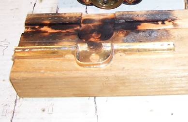
Photo# 6 ”Side Beam Soldering Jig”
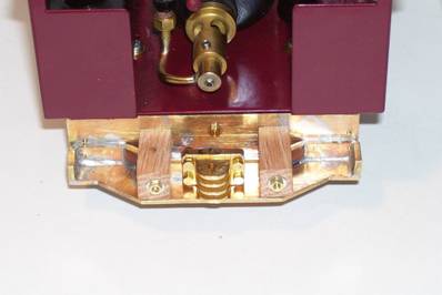
At the front edge of each side beam, there is a front beam support plate .4375” wide x .561” deep x .0625” thick, once it’s bent to shape and drilled for the 2 truss rods, it is soldered to the front of the C-channel. The side beams are held in place by 2-56 hex head screws, one at the angle plate connector to the rear end beam, one at the forward end and four in the side beam’s center section, all drilled and tapped into the under carriage.
The Front Buffer Assembly
The front buffer assembly is made from 3 short built-up C-channel pieces .4375” wide x .05” thick, 2 oak beams drilled to receive the 2 lateral truss rods and 2 brass rods, shaped to the front buffer pattern and each end threaded for 2-56 nuts. The brass rods are .086” diameter.
I did an extensive fit checking for this step to get the angles right. I cut a piece of wood to represent the dimensions of the Cricket’s under carriage. All of the oak beams & C-channel pieces were milled on my Sherline vertical mill to get the proper dimensions and angles.
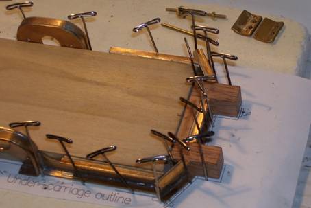
Photo# 7 “Front Buffer Pieces Fit Check with Side Beams”
While everything was still held in place, I soldered the 2 outside C-channel front buffer pieces to the side beam C-channel and the front beam supports, making for an easier disassembly, if needed. Also the Journal Frames were soldered to the side frames at this point.
Photo# 8 “Completed Side Frame”
The center section of the front buffer is made from 3 oak pieces, escutcheon pinned and CA’d together. The center C-Channel piece is attached to the adjacent oak piece, using hex head lag screws.
Through the end of each of the oak beams is a hole drilled its length for a rod, threaded for 2-56 nuts and washers. Matching holes are drilled & tapped through the under-carriage for these 2 rods; attaching the front buffer assembly to the under-carriage.
Photo# 9 “Front Buffer”
Photo# 10 “Side Beam Fitted with Front Buffer”
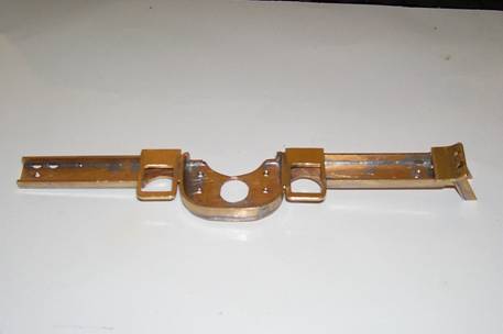
Fabricating the Rear End Beam & Coupler
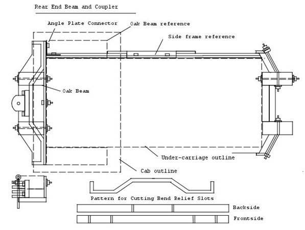
Photo# 11 “Rear End Beam & Coupler Dwg.”
The rear end beam is fabricated from brass plate, .125” thick x .961” wide x 3 5/8” wide as the base onto which .311” wide x .125” thick strip brass is soldered on edge to match the pattern. All of this is soldered to a brass backing plate, .062” thick x .750” high x 3.591” wide. I used a brass “Link & Pin type Coupler Pocket for Engines” TD-177 by Trackside Details attached to the end beam using 2-56 hex head screws. Like the front buffer, the under-carriage frame’s simulated oak beams protrude. Through the end of each of these oak beams I drilled a hole along its length for a rod; each end threaded for 2-56 nuts and washers. The backing plate and under-carriage is drilled for these 2 rods for attaching the rear end beam to the under-carriage.
Photo# 12 “Rear End Beam”
Photo#13 “Side Frame Fitted with Rear End Beam.”
Making the Decking
For the Deck Beams I used Poplar wood. The deck beams are 11/32” square x 2 31/32” long. The center of each beam is milled out so that a single beam covers no only the top of the under-carriage, but also covers the sides. By doing this, only 3/32” is added to the height of the under-carriage. Cutouts have been made for each of two boiler supports and the steam motor’s mounting bracket. Some additional relief for the middle boiler band screw is also needed. In the interest being non-evasive to the existing under-carriage’s powder-coat finish, all of beams are attached (CA’d) to a 2” wide sheet of .006 brass shim material. The shim material extends under the forward boiler support, so that when re-attaching the boiler support, the deck beams are all secured in place as a unit and is removable. Although to install or remove the deck, the flywheel needs to be removed first and the rear boiler support’s screw needs to be loosened.
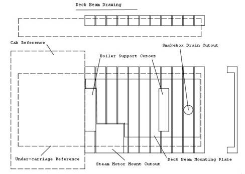
Photo# 14 “Deck Beam Dwg.”
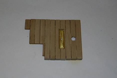
Photo# 15 “Deck Beams Mounted on Brass Backing”
The Side Tanks
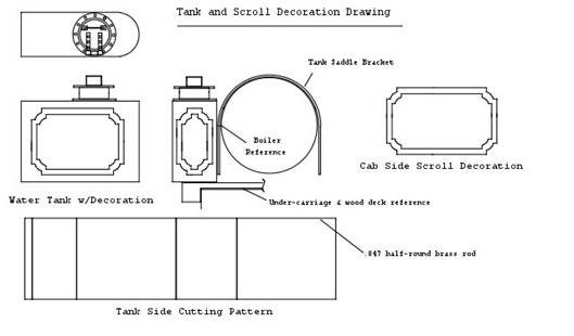
Photo# 16 “Side Tank Dwg”
I used .010” brass sheet stock to make the 1.375” high x .750” wide x 2.0” long tanks. The brass sheet was bent around a wood form I made for the rounded front of the tanks. A half-round clamping piece was cut from ľ” O.D. aluminum tubing.
Photo# 17 “Wood Form & ˝ Round Clamping Piece”
In conjunction with a c-clamp, it was used to hold the brass work piece tightly to the wood form for soldering the tank’s top and bottom in place.
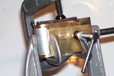
Photo# 18 “Brass Workpiece Clamped on Form”
Soldering was done with a butane micro-torch. Once the soldered, the wood form was removed and the end portion of the tank was bent over to form the tank’s end and the final soldering was done.
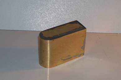
Photo# 19 “Completed Tank”
A Water Hatch, TD-37X from Trackside Details, was soldered on the top after reducing its height by 3/16” using my lathe. I created a soldering mandrel from a piece of 7/16” dia. hardwood doweling. Using my lathe, I turned the dowel down to a tight fit for the main barrel of the Water Hatch, then turned down the end of the dowel down to fit the 7/32” hole I drilled in the base of the Water Hatch. This yielded a perfect way to precisely hold the 2 pieces of the Water Hatch together for soldering.
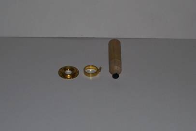
Photo# 20 “Water Hatch & Soldering Mandrel”
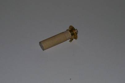
Photo# 21 “Ready for Soldering”
A tank support (saddle bracket) to suspend the tanks from the boiler was fashioned from .05” thick x .1875” wide brass strip and attached to the tanks using JB Weld epoxy. This makes the side tanks removable. I decided on using epoxy because I didn’t want mistakenly unsolder any of the tank’s joints. I secured the epoxy joint with mechanical joint, a short 1/8” dia. pop-rivet. I also used JB Weld epoxy to attach the Water Hatch to the tank top. I had to add a .2750” spacer behind the flywheel to move it outboard on the crankshaft to get clearance for the tank.

Photo#22 ”Completed Side Tanks”
The Finishing Steps
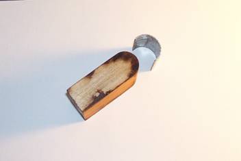
All of the new brass pieces were primed with Rust-Oleum brand Self-Etching Primer. The frame, buffer & end beam brass parts were painted with Rust-Oleum Hi-Heat Matte Black Enamel. The tanks were painted with Dupli-Color Gloss Black Ceramic Engine Enamel. The tank’s saddle bracket was left natural brass color to match the existing boiler bands. All wood pieces were stained with a dilute India ink, then I sealed with Krylon Clear Matte polyurethane. And lastly, the vinyl transfer scrolls were added to each of the tank’s front and outside facing surfaces, and to the existing cab sides and back.
Builder’s pictures & first run at the June 2009 Big Trains Show in Ontario, Ca.


